Image 1
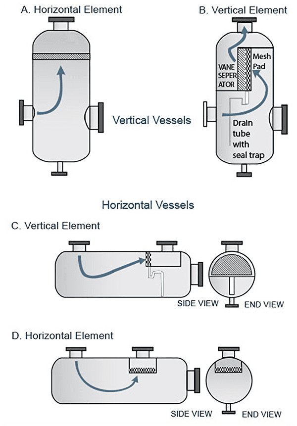
Several factors must be considered when deciding the configuration of vessel internals. The first step is to determine the cross-sectional area needed. Then alternative geometry and shape appropriate for both the vessel and plant location is selected. Image 1 shows the most typical, but by no means complete, configurations. Demister pads can be of virtually any size or shape to accommodate all factors.
Simplified views of typical demister pad configurations in separator vessels

Image 1

Image 2
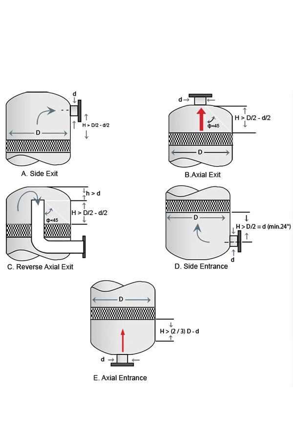
The performance of the demister pad depends on an even velocity distribution over the cross-sectional area. Representations for specific cases are illustrated in image 2. Small velocity differences are acceptable, but should be minimized at the design stage. Otherwise, some regions of the demister pad may be subjected to heavy loading leading to re-entrainment while other regions are unused.
Generally, the demister pad is located at the upstream of the outlet nozzle with insufficient disengagement space. Vapor tends to channel through the pad in the region closet to the outlet nozzle and peripheral regions of the pad remain unused. To rectify this, our engineers apply an integral flow distributor which is welded to regions of the downstream face of the pad. This technique allows the engineer to selectively increase the pressure drop through regions of the pad likely to suffer from channeling, and is cost effective.
