Demister pad – tie wire installation
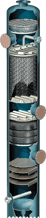
Demister pad is a device used for removing entrained mist from a gaseous or vapor stream and is designed to provide excellent gas-liquid separation performance in the process of distillation, gas absorption and stripping condensation, gas compression, dehumidification and drying as well as the removal of spray and desalination. A correct and proper installation is the way to realizing this performance. In this article, we would like to introduce some helpful suggestions to help you simplify your installation steps and achieve best installation results.
Preparations
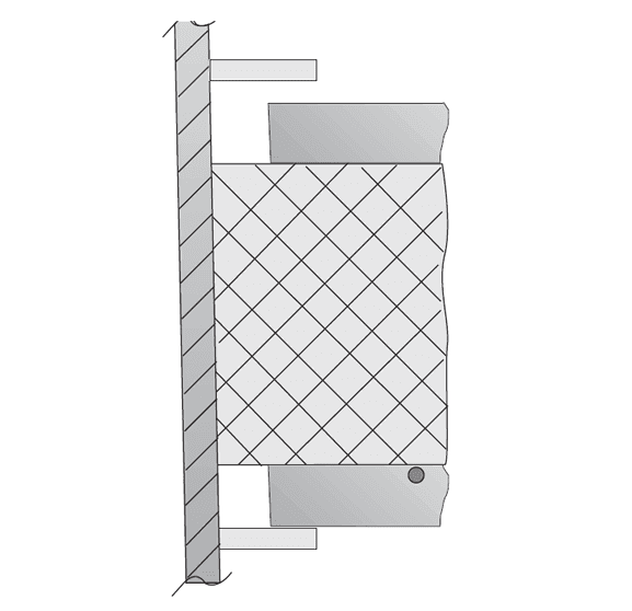
Generally, the demister pad is manufactured slightly oversized to accommodate any deformation of the vessel and to ensure a tight fit between the demister pad and the vessel wall to prevent any gas leaking from the contact surface. Any gaps between the vessel wall and the demister pad will lower its separation efficiency and performance. A tight fit ensures optimum gas-liquid separation performance.

Keep in mind the mesh pad will be manufactured slightly larger than the diameter of the vessel to be installed into.

Before removing the existing demister pad, it is highly recommended to study how the existing one was installed. Check the existing demister pad if there are signs of excessive corrosion or fouling and if there are dislodged sections.
If the existing pad was built in sections, pull the center section first. As a properly installed demister pad fits tightly to the wall of the vessel, a larger pulling force is required to remove the center section. Once the center section is removed, the other sections will be removed much more easily. Remove one section at a time. And then remove other sections one by one to prevent loose sections fall off.
After removing all sections, check all support structures carefully if there are cracks, excessive corrosion signs, and damaged support hardware. Repair all defects that might impair the proper installation and operation of the new demister pad. Make sure the existing supports are suitable for your new one, pay attention to what hold down hardware you will be employing. You may orient or turn the new pad into the exact position of the demister pad to be removed for reference purposes later.
Hold Down Options
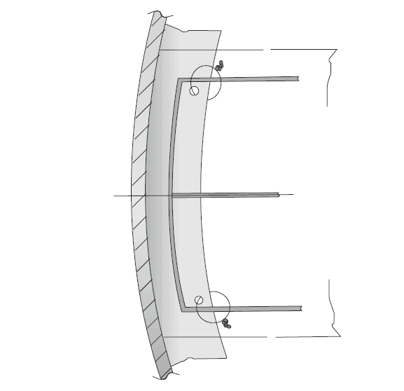
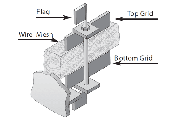
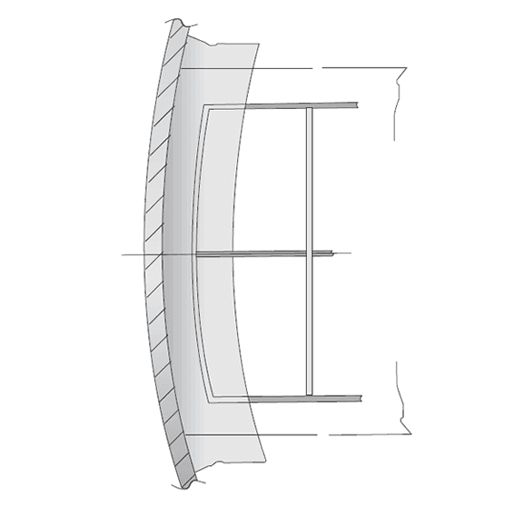
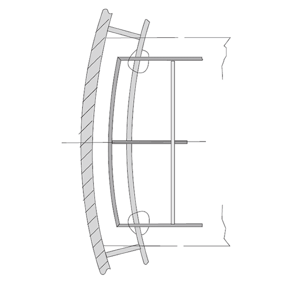
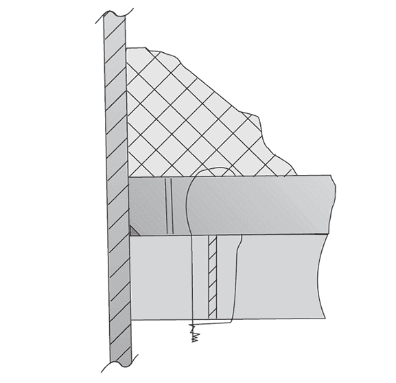
Tie Wires
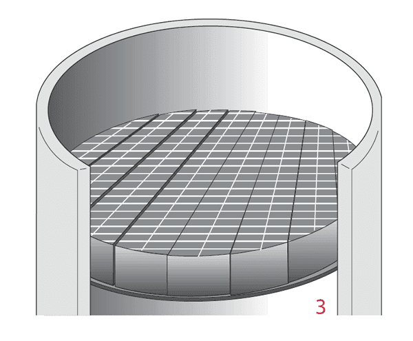
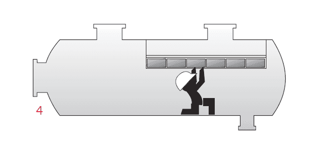
Tie wires are the most common and simplest way of attaching the demister pad to its supports. The tie wires are typically 0.051" in diameter and are made of the same material as the mesh. This can be achieved by looping the tie wire between the bottom support grid and the annular ring hole and twisting the ends to tie it in place. (Do not run the wire through the mesh, just the support and grid.) Tie down the four corners of the grids in each section. Annular ring hole spacing is typically 4" to 5" apart with 1/4" diameter holes.
Demister pad – tie wire installation
Demister pad – tie wire installation details
For plastic mesh materials, use several loops of tie wires.
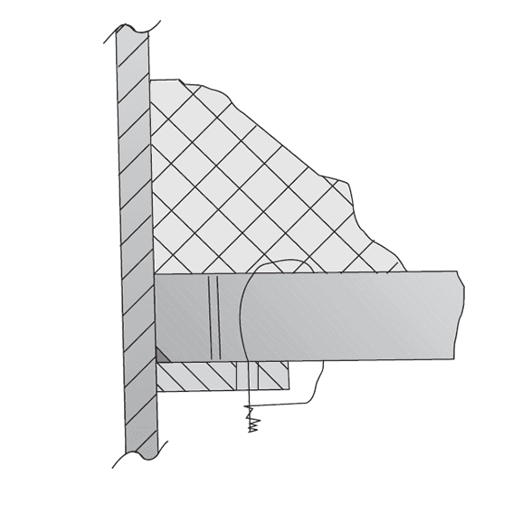
J-Bolts
J-bolts can be used instead of tie wires and are stronger. The hook portion of the "J" connects around the demister pad’s bottom grid, extends through a clamp or holes in the annular ring and is secured by a nut and lock nut. Once again, 4 bolts should be used per section. Another variant is a "welded stud."
Demister pad – J-bolt installation

Demister pad – J-bolt installation details
Please Note: make sure your J-bolt connections are secure and can withstand heat and vibration. Double nuts or locknuts are highly recommended.
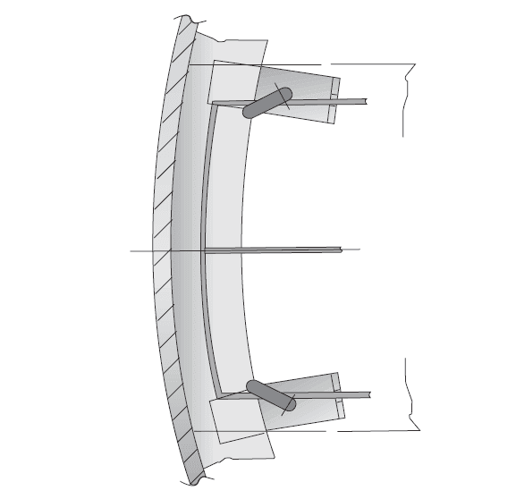
Latch Keys
Latch keys can be used to secure a demister pad when having to work from the stop, and access to the bottom is not possible. Simply turn the flag toward the vessel wall and tighten the double lock nuts.
Demister pad – latch key installation
Dual Support Rings
Dual support rings have removable ring sections on the manway side. When the last demister pad section is installed, bolt the ring sections into place. Dual support rings are more common for topside installations but are also used in bottom installations. Dual support rings also help prevent wall bypass.
Demister pad – dual support ring installation
Demister pad – dual support ring installation details

Demister pad – dual support ring removable section installation
Offset Rings
Offset rings are held away from the vessel wall by a standoff. Secure the demister pad using tie wire or J-bolts and clamps.
Demister pad – tie wire with offset ring installation
Demister pad – tie wire with offset ring installation details
Hold Down Bars
Hold down bar bolts into position above the demister pad after it is installed and is an effective mean to keep the demister pad pieces intact.
Demister pad – hold down bar installation
Basket Cages
Basket cages for one-piece demister pad are held in place by the vessel top flange. You simply slide the cage on top of the demister pad and fasten the head or top flange, when installing one-piece demister pads.
Demister pad – basket cage installation
Expansion Rings
Expansion rings can be used for either a support ring or a hold down ring when welding to the shell is a problem.

Demister pad – expansion ring installation
For demister pad installed in small diameter vessels with a flanged top, the pad must be made into two sections to clear hold down bar clips welded to the shell.
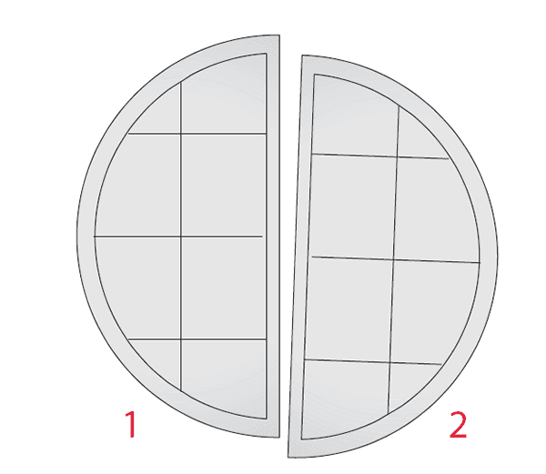
Demister pad in small vessels is separated into two sections to clear hold down bar clips welded to the shell.
Hold down method with exit above demister pad
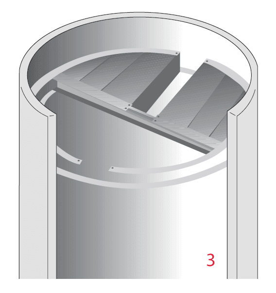
If installers must exit from manway above the demister pad, install demister pad tie wiring from below working from the outer sections toward the center. Install the last section from the top and secure to adjacent sections by placing 3 hold down bars (1/4" x 1" flat bar) across the last section installed and tie wiring or J-bolting to adjacent sections.

Manway section and hold down bars for demister pad installation

One Piece Demister Pads
Any fastening method except J-bolts can be used for one piece demister pads. For new vessels make sure the vessel walls are smooth and free of weld splatter and other debris before pushing the demister pad into the vessel. Keep in mind the mesh diameter should slightly exceed the vessel diameter to ensure a snug fit as shown to the right.

One piece demister pad installation method

Multi-section demister pad with single support ring installation step 1

Multi-section demister pad with single support ring installation step 2
Multi-section demister pad with single support ring installation step 3

Multi-section demister pad with dual support rings installation step 1

Multi-section demister pad with dual support rings installation step 2
Multi-section demister pad with dual support rings installation step 3

Multi-section demister pad with dual support rings installation step 4

Multi-section demister pad with dual support rings installation step 5

Multi-section demister pad with dual support rings installation step 6

Multi-section demister pad with dual support rings installation step 7

Multi-section demister pad with dual support rings installation step 8

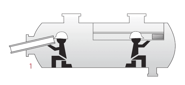
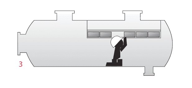
Installation procedures of vertical demister pad in horizontal vessels

Top view of the demister final section installation diagram
Horizontal demister pad in horizontal vessels installation step 1

Horizontal demister pad in horizontal vessels installation step 2
Horizontal demister pad in horizontal vessels installation step 3
Horizontal demister pad in horizontal vessels installation step 4
Final Notes:
Make certain and check your work when all installation procedures are finished.